ALIGNING THE CCD IN AN SXVR CAMERA
All SXVR (and some SXVF) cameras incorporate a set of ‘antagonistic screws’ in the faceplate to allow the user to set the CCD accurately parallel to the focal plane of a telescope. Although the cameras are set up at the SX factory, it is sometimes necessary to refine the setting to optimise the focus across a large CCD. Here I will describe how the cameras are set up at the factory and how you can make adjustments at the telescope.
1) The factory adjustment method:
Our method involves reflecting laser light from the CCD surface and observing how the reflections rotate on a screen when the camera is revolved. The CCD is properly aligned when the bright reflection from the CCD cover slip is stationary on the screen, despite rotating the camera through 360 degrees. This is the jig that we use:
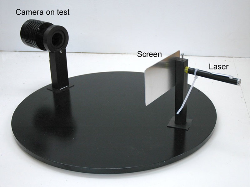
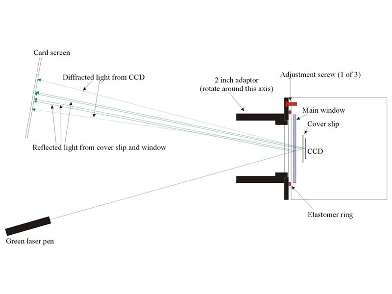
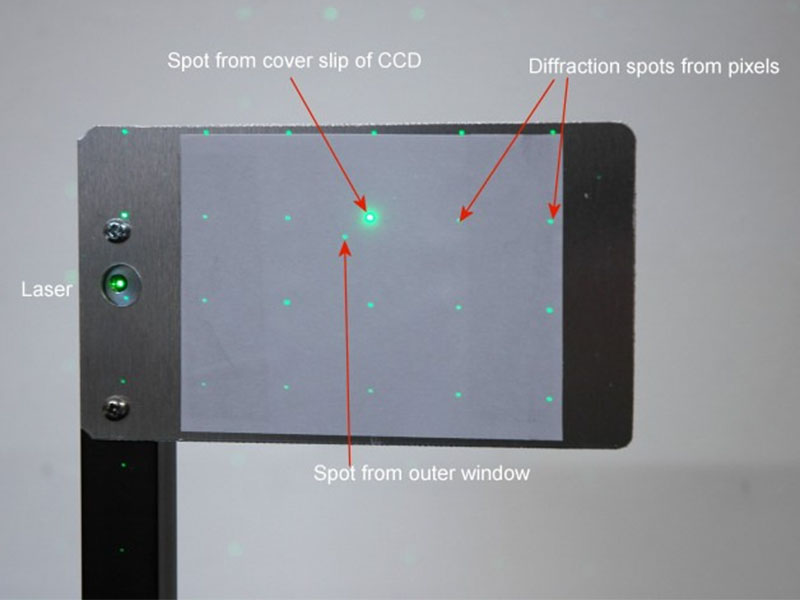
The collimation process involves rotating the camera about the faceplate axis, using a standard 2 inch ‘nose piece’ as the bearing. If you can clamp the nose piece, it might be sufficient to rotate the camera on the T thread, although this is certain to be a bit ‘wobbly’. As the camera is rotated, the reflected spot pattern will revolve and you can judge where the rotation centre is on the screen. The reflection from the CCD cover slip is normally the brightest spot and sits on top of the central reflection from the CCD chip surface – you may see another spot which is nearby but not usually aligned with the diffracted grid of spots. This is a reflection from the outer camera window and is not important for collimation purposes.
First, loosen the three set screws so that the plate is ‘floating’ on the elastomer O ring. Now tighten the three silver screws so that the O ring is fairly firmly gripped and the plate is roughly parallel to the camera front. Now mount the camera by the nose piece, turn on the laser, and then rotate the camera to observe the motion of the reflections. I suggest rotating the camera until the cover slip spot is as far to the right of the centre of rotation as it goes during a rotation. You should then tighten the adjustment screw which is furthest right at that time (or loosen the leftmost screw a little) – this will move the reflection leftwards and reduce the offset from the rotation axis. Rotate several times and adjust as above until the cover slip spot is essentially stationary when you rotate the camera.
Retighten the set screws and recheck the collimation to ensure that it is still satisfactory.
2) Setting up on the ‘scope
‘CCD Inspector’ is a very useful program for optimising your camera collimation, but you do not need this to do a good job. I use the following method:
1) Loosen the setscrews and adjust the silver screws for a firm pressure on the O ring – try to get them equally tight, but with some latitude for movement.
2) Put the camera on the scope and aim at a reasonably dense star field – a view of the Milky Way will do fine.
3) Start taking short exposures (1-10 seconds) in 1×1 binning, using ‘continuous’ mode and adjust the telescope so that one
edge of the field is in accurate focus. It is likely that star images at the opposite edge are soft, or quite badly defocused, showing that the CCD is tilted.
4) Adjust the focus a little and determine if the ‘soft’ edge gets sharper when you rack the camera in, or when you rack it out. If it needs racking in, then the soft edge is further from the objective and vice-versa if you have to rack it out.
5) The image on the CCD is inverted in most cases and so the right hand side of your computer picture corresponds to the left hand side of the camera faceplate. If the badly focused edge is at the right side of your screen and the focus needed to be racked in to improve it, then try tightening the screw closest to the left side of the camera. Refocus and see if things have got better – hopefully yes!
6) Keep circulating around the screws as necessary until the difference in focus at all points in the image is imperceptible. This needs a little practice to master, but is not very difficult. Try to keep all the screws fairly tight, or the O ring might not keep out all the ambient light.
7) Finish by re-tightening the set screws.